Transformer Testing
The purpose of this article is to provide a list of the standard battery of tests performed on reconditioned and new transformers, while also providing an introductory explanation of the purpose and scope of the most common routine factory and diagnostic field tests. Factory testing is performed according to IEEE C57.12.00 and IEEE C57.12.90 standards for liquid-immersed distribution, power, and regulating transformers and IEEE C57.12.01 and IEEE C57.12.91 standards for dry-type distribution transformers and power transformers.
Test Classifications
(as defined in IEEE C57.12.80-2002):
Routine Tests
Tests made for quality control by the manufacturer on every device or representative samples, or on parts or materials as required, to verify during production that the product meets the design specifications” (Section 3.393).
IEEE C57.12.00 & IEEE C57.12.90 (Liquid-Immersed)
IEEE C57.12.01 & IEEE C57.12.91 (Dry-Type)
Design Tests
Those tests made to determine the adequacy of the design of a particular type, style, or model of equipment or its component parts to meet its assigned ratings and to operate satisfactorily under normal service conditions or under special conditions if specified, and to demonstrate compliance with appropriate standards of the industry. Syn: type test (IEC)” (Section 3.99).
IEEE C57.12.00 & IEEE C57.12.90 (Liquid-Immersed)
IEEE C57.12.01 & IEEE C57.12.91 (Dry-Type)
Other Tests
Tests so identified in individual product standards that may be specified by the purchaser in addition to design and routine tests (Examples: impulse, insulation power factor, audible sound.)” (Section 3.311).
IEEE C57.12.00 & IEEE C57.12.90 (Liquid-Immersed)
IEEE C57.12.01 & IEEE C57.12.91 (Dry-Type)
Transformer Turns Ratio (TTR)
Every two-winding transformer has a ratio. The ratio is the relationship between the number of turns on the primary and secondary windings of a transformer. To understand the basic function of a transformer, you could think of it as a ratio box. No matter what you put into it, it will always produce a result proportionate to the ratio. An example of a 1:1 ratio would be where the input and output voltages are the same (for every 1 turn on the primary winding, you would have 1 corresponding turn on the secondary). For a 2:1 ratio, the secondary (output) voltage is half of the primary (input) voltage—for every two turns on the primary winding, you have one corresponding turn on the secondary side, and so on. If you applied 10 volts to the primary of a transformer with a 2:1 ratio, the result would be 5 volts on the secondary; if you put 20 volts into the same transformer, you would get 10 volts out. This predetermined relationship between the primary and secondary windings for any given transformer is called the calculated ratio. The turns ratio test (TTR) is performed to confirm that the unit’s tested ratio lies close enough to the calculated value per IEEE standards.
To find the calculated ratio, divide the rated primary phase voltage by the rated secondary phase voltage as depicted on the nameplate of the transformer. When determining the calculated ratio for a transformer, it is important to refer to the coil (phase) voltage—the phase voltage determines the number of turns at the transformer coils. For a delta-connected winding, the phase voltage is the same as the line-to-line voltage, but for a wye-connected winding, the line and phase voltages are different. For a wye winding, the coil or phase voltage is represented by the second smaller number (line-to-neutral) and is obtained by dividing the phase-to-phase voltage by the square root of 3 and is written as follows: 13200 Y/ 7620. For example, a transformer that is 13200 Y/ 7620 - 480 Y/ 277 would have a calculated ratio of 27.51, whereas a transformer with a delta primary, such as 13200 D - 480 Y/ 277, would have a calculated ratio of 47.65.
When a transformer is built at the factory, the actual ratio at the coils will differ slightly from the calculated value due mainly to the fact that you cannot have partial turns. IEEE standards allow a 0.5% variance above and below the calculated value for tested ratios. This standard is used by Maddox, and it is the same standard employed by field testing companies and associations such as NETA. Maddox performs a standard TTR test on all used units when they are brought into inventory and again after the reconditioning process is complete. Test values are provided for all tap positions on reconditioned units.
Winding Resistance
A winding resistance test helps evaluate the condition and quality of the current-carrying path of the windings in a transformer. For new factory-built padmount transformers, this test is only required for sizes above 2,500 kVA (IEEE C57.12.00), but Maddox utilizes the winding resistance test for all reconditioned medium-voltage units. Winding resistance provides essential diagnostic information, which can aid in evaluating whether a unit is suitable for repair or reconditioning. Issues such as loose internal connections, faulty tap changers, open circuits, and broken conductor strands or crimp connections may be identified with this test. In the case of a delta connection, measurements are made phase-to-phase (H1-H2, H2-H3, H1-H3). With a wye connection, measurements may also be made phase-to-phase (H1-H2, H2-H3, H1-H3), as well as phase-to-neutral (H1-H0, H2-H0, H3-H0).
This test is measured in ohms, and the value is typically low (tenths or hundredths of a decimal). Keep in mind that when this test is performed (especially in the field), it is typically done at the bushings of the transformer. As a result, measurements will include any components in the current-carrying path of the windings, such as tap changers, fuses, switches, and cable leads, which may affect test results. A questionable reading may not always indicate a problem with the coils themselves. For instance, if one phase of a transformer has a significantly longer section of internal bus work between the bushing and the winding lead it connects to, you may see a higher measured value across that particular phase. In this case, the test data would not indicate a problem, but a simple fact inherent to the mechanical design of the unit.
The same type of variance, however, could show up on a phase with a loose or frayed cable connection at the tap changer, where the variant reading would indicate a mechanical problem that would need to be addressed during the reconditioning process. For this reason, the proper performance of a winding resistance test requires a proficient mechanical knowledge of the internal workings of the transformer, as well as an aptitude for evaluating the available test data. Results between phases that fall within 5% of each other are generally considered acceptable (IEEE Std 62-1995, p. 7, section 6.1.1).

TTR (left) and Winding Resistance (right) test sets.
Insulation Resistance (Megger)
While insulation resistance (or megger) testing is not recognized by IEEE for determining pass/fail criteria on newly manufactured transformers (discussed in the following paragraph), it is a useful supplementary test for units that have spent some time in service out in the field. As the title indicates, the purpose of this test is to determine the quality of the insulation on a piece of electrical equipment. Insulation resistance testing is used on a variety of electrical apparatus, such as conveyors, motors, fans, refrigerators, HVAC systems, and cables. In this test, we are measuring the resistive capability of the insulation material within the transformer between windings and core ground, commonly measured in megohms. The test is performed by applying a specified DC voltage through the conductor(s) of the transformer. Over time, the insulation may age or degrade from factors such as overheating, external physical stress, or moisture. This degradation can lead to a reduced capability of the insulation to withstand the required operating voltages of the transformer.
Transformers do not see the kind of mechanical and physical stressors common to motors and cables in a raceway. Due to the design of distribution class transformers, test results can yield inconclusive values and may puzzle a field technician who is used to meggering stand-alone cables in a raceway. Core grounding methods and components such as switches, fuses, and tap-changing devices may also affect the results of insulation resistance testing on transformers. For this reason, insulation resistance tests for transformers should be treated as supplementary to the battery of standard routine tests outlined under IEEE C57.12.00, and not the be-all and end-all of determining a good transformer from a bad one. Insulation resistance is performed on the high-side windings to low-side windings, high-side windings to ground, and low-side windings to ground.

Workers performing Megger on a dry-type transformer.
Impedance Voltage (Positive Sequence), Load Loss
With an impedance test, we are measuring the losses in the transformer: the watts/power wasted or lost during electrical operation. The quality of construction along with the type of materials used in the building of the transformer’s coil assembly play a role in determining the results of this test. Unlike the insulation and winding resistance tests, which serve as supplementary evaluations for distribution class transformers, the impedance/load loss test yields concrete results that can be taken at face value. This test may be used to confirm the design values for a given unit where a certain number of losses is requested by a customer on a new factory-built unit.
IEEE lists standardized impedances for distribution class transformers above 500 kVA at 5.75% (+/-7.5%), but sometimes, customers will request something different. This can be largely accomplished with the design itself. The impedance (%IZ) of a transformer is affected by the resistive (%IR) and reactive (%IX) components of a transformer. It is during this test that the reactive and resistive components of impedance are identified, as well as the resulting X/R ratio of a unit. For reconditioned transformers, these values will be determined by how the unit was originally manufactured at the factory. Impedance/load loss testing is a standard routine factory test (IEEE C57.12.00), which is required for all new factory-built padmount distribution class transformers, and it is performed on all transformers that are repaired or reconditioned by Maddox. The tolerance from the specified value for two-winding transformers is ±7.5%; for zigzag units, autotransformers, and transformers with three or more windings, the tolerance is ±10% (IEEE C57.12.00-2020, p. 64, 9.2).
Excitation, No-Load Loss
With an excitation test, we are testing the flow of magnetic flux in the transformer core. If the words magnetic flux sound a bit too technical, think about a simple magnet with two ends or poles (one south and the other north). If you sprinkled iron shavings on a table near the magnet, you would see the iron shavings line up in long oval loops springing from one end of the magnet to the other (these invisible phenomena are referred to as magnetic lines of flux). These magnetic fields are all around us, and it is this same principle which is behind the invention of the directional compass. A transformer’s ability to produce these lines of flux is what we are after here in the excitation test. To perform this test, voltage is applied to the low side of the transformer windings with the high-side windings open, which allows the amount of magnetic flux required for operation to flow through the core.
Another way to think of excitation is to think of it as the amount of work required to start the transformer. The quality of the core and assembly and its construction influence how much excitation is needed during energization. Imagine trying to roll a car with a dead battery down the street to a nearby parking lot. You would have to do some amount of work to get the car going, which would require a bit more heaving and grunting in the beginning; this extra heaving and grunting would merely be spent in getting the object out of its stationary state. In the same way, a poorly built (or damaged) core assembly will require more “heaving” and “grunting” when the transformer is energized. The additional work required at startup is what we refer to as inrush current. The excitation current and the associated no-load loss are the power that keeps the core energized during normal operation. The quality, orientation, and construction of the laminated core steel in a transformer will determine the exciting current. For new distribution class transformers, the DOE has set minimum efficiencies in distribution class transformers up to 2500 kVA.
Excitation/no-load loss testing is another standard factory routine test for new factory-built transformers (IEEE C57.12.00), and it is an essential part of the repair and reconditioning process at Maddox. The presence of a higher-than-normal exciting current often can lead to the discovery of internal problems, such as shorted turns, a damaged core assembly, or a faulty tap changer. Some of these issues can be fixed in the repair process. This test is also used as a baseline for determining the viability of a unit for repair or reconditioning, and it is performed on all 3-phase distribution class transformers.
Learn more about transformer cores in this article.

Loss testing being performed.
Phase Relation
The phase relation test confirms the angular displacement and phase sequence between windings in a 3-phase transformer. In layman's terms, it confirms the coils are connected correctly inside the transformer tank. For example, if you apply a voltage across H1 and H2 at the primary winding, you would expect to measure a corresponding voltage across X1 and X2 at the secondary winding. Let’s say for the sake of this example that when you applied a voltage across H1 and H2, you instead found the corresponding voltage across X2 and X3 on the low winding. In this case, the primary and secondary windings would be out of sequence, and the internal winding connections would need to be fixed accordingly.
With two-winding transformers, the coils may be connected in delta or wye. For a 3-phase transformer connected delta on the primary and wye on the secondary, a 30-degree phase shift will typically be present, which can be either leading or lagging. For a transformer connected delta on the primary and delta on the secondary, there is typically a zero-degree (or no) phase shift (the same scenario exists where a wye connection is on both the primary and secondary side). The phase relation test confirms that the internal connection of the coils matches the vector grouping diagram on the nameplate of a given transformer. This information is vital to the proper operation of an electrical system—especially where multiple units are tied together. Verifying proper phasing is a basic part of the repair and reconditioning process. This test is another routine test required for all new factory-built transformers (IEEE C57.12.00), and it is performed on all units brought into the Maddox facility for repair and reconditioning.
Leak Test
Every liquid-filled transformer is tested to verify the transformer tank will hold and maintain pressure when put into service by adding 5 PSI of pressure to the tank and leaving it for 24 hours. A visual inspection then is made to verify that no fluid leaks exist around any gaskets or seals, and that no pressure has left the tank by checking the pressure gauge when possible. In the case where a radiator was repaired or replaced, additional care is taken to verify a successful repair that will hold up to usual service conditions in the field.

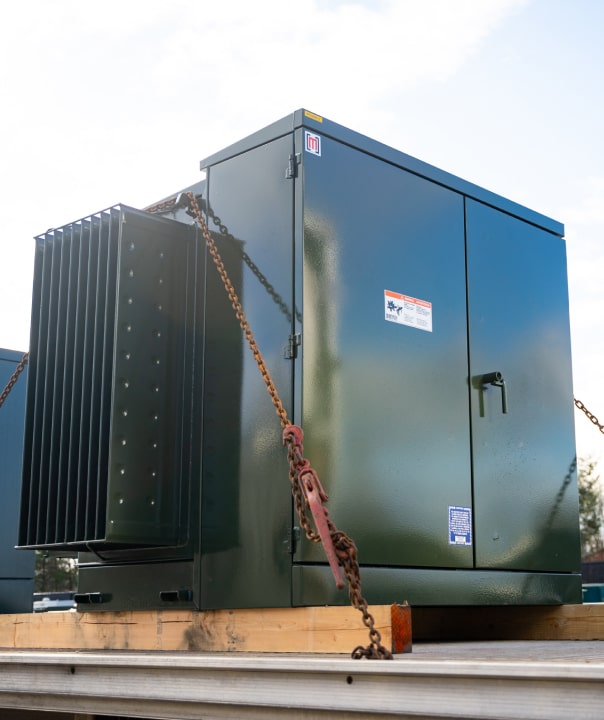
Liquid-filled transformer awaiting shipment.
Applied Potential
The applied potential test is currently not part of the standard battery of tests for reconditioned transformers. It is a routine test per IEEE C57.12.00, and applied potential is performed on all new factory-built Maddox transformers. The purpose of this test is to ensure the integrity of the insulation system in a given unit by putting the insulation under short-term stress via an overvoltage. For this test, a voltage is applied and gradually increased between the windings being tested, with the starting voltage being no more than one-quarter of the full value. The duration of the test is one minute at the specified test voltage, as outlined in IEEE C57.12.90. This test is often omitted in the field for in-service transformers due to the difficulty of achieving the required test voltage levels. Applied potential testing is designed to fail an insulation system that is already compromised; it is generally agreed that it will not result in damage or failure when performed on a unit with good insulation.
Induced Potential Test
The induced potential test is another overvoltage test, like the applied potential test. It is also a routine IEEE test performed on all newly manufactured transformers. Like applied potential testing, this particular test is currently not included among the list of tests performed on reconditioned transformers. To perform this test, a voltage “greater-than-rated volts per turn to the transformer” (IEEE C57.12.90-2021, p. 62) is applied and gradually increased for a designated period of time, depending on the frequency at which the test is performed (the frequency supplied must be raised to prevent over-excitation of the core, as the applied test voltage is significantly higher than the rated voltage). The formula for establishing the minimum test frequency is set forth in section 10.7.2 of IEEE C57.12.90.
Impulse Test
Impulse testing is another test that is only performed on newly manufactured units at the factory. The purpose of this test is to analyze a transformer's ability to withstand large voltage surges, as would be common in a typical electrical system. During normal service conditions, transformers are often exposed to sudden high-voltage spikes resulting from lightning or the operation of switches. Along with induced and applied potential tests, we are again testing the dielectric strength of the insulation system in the transformer. In the case of lightning, the voltage wave can take a variety of forms. For this reason, the impulse test is designed to imitate both the form of the wave and the succession in which the various wave shapes may occur. For class I power transformers, these are one reduced full wave, one full wave, two chopped waves, and two full waves. For pad-mounted distribution transformers, these are one reduced wave and one full wave.
Insulation Power Factor Test
Power factor testing is most commonly associated with larger class I and II power transformers, and it is a standard routine test for power units per IEEE C57.12.00. It is important to note that this test is not recognized by IEEE as an accepted method for determining pass/fail criteria on distribution class transformers. The test code laid out in IEEE C57.12.90 also notes the difficulty and potential problems associated with attempting to establish absolute values to apply across the board for this test on distribution class transformers (See Notes 1, 2 & 3 of Table 4, IEEE C57.12.90-2021, p. 67). Although test results can be difficult to interpret at times, power factor testing provides a diagnostic benefit when comparing test data for a single unit over a period of time. For example, if a more recent set of test results contrasts significantly with data from an earlier test for the same unit, this could alert a technician to the possibility of an issue that may need attention. The use of an initial stand-alone test to establish pass/fail criteria in distribution class transformers, however, is not advisable. Due to the physical construction and the presence of other ancillary components within the path of the test voltage, such as tap changers and switches, results can vary widely for distribution class transformers.
While power factor testing is not performed under the standard battery of tests required by IEEE C57.12.00 for smaller transformers (generally below 10 MVA), it is required by NETA on all distribution class units. It’s important to note that the test values suggested by NETA for insulation power factor testing exist in lieu of the absence of an agreed-upon standard (See Table 100.3, NETA Standard for Maintenance Testing Specifications for Electrical Power Equipment and Systems). The values established by NETA do not remove the extant difficulties expressed under IEEE C57.12.90, but rather act as a general guide for technicians performing this test in the field. When field test values fall outside what is recommended by NETA, the next course of action should be to perform the remaining battery of standard tests for field commissioning and evaluate the results. A field technician may need to sign off on his end for any values that do not fall within NETA’s recommendations, and it may be necessary for Maddox to add clarification or verify that the unit’s test results are within acceptable limits according to factory standards. Insulation power factor testing is a standard test for all new and reconditioned class I power transformers supplied by Maddox.
Additional notes:
- Field testing conditions: testing should never be conducted when the tank is under vacuum; the dielectric strength of the insulating material is severely reduced under negative pressure (IEEE Std 62-1995, p.6, section 5.3.4).
- Testing voltages: for windings in a grounded wye configuration where the insulation is graded or reduced for applications on grounded systems, the test voltage should be applied based on the lowest insulation level of the tested winding (IEEE Std 62-1995, p.6, section 5.3.3).
- IEEE tolerances for quoted losses: sometimes, the specified no-load and load loss values may be slightly lower than the actual tested values after production on new transformers. This is not uncommon, since an exact value is difficult to attain every time. For this reason, IEEE allows a certain tolerance for specified losses. For specified losses, the no-load losses may not exceed 10%, and the total losses may not go above 6% (IEEE C57.12.00-2021, p.62, 9.3).