What are transformer bushings
Transformer bushings are the medium through which electrical current passes in and out of the transformer. Transformer bushings provide an effective path for electrical current to enter the transformer and insulate that path from other nearby conductive materials
There are two main types of bushings used in padmount transformers – live front and dead front bushings. With live front, a part of the conductor is exposed, whereas with dead front, the conductor is completely enclosed inside an effective insulating material such as epoxy, EPDM rubber, and/or nylon resin.
Learn more about live front and dead front bushings
Difference between Primary/HV and Secondary LV bushings

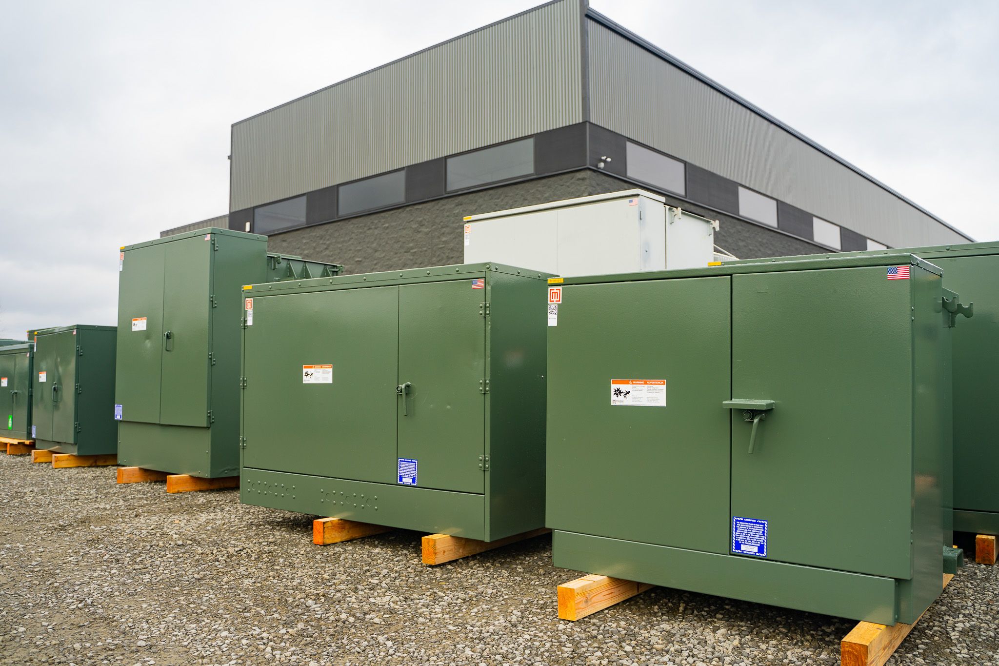
In padmount transformers the primary bushings are located on the left hand compartment in the cabinet, and the secondary bushings are in a right hand compartment. The two compartments are separated by a metal barrier.
The difference between primary and secondary bushings on padmounts is the voltage and amperage they are designed to carry. The primary / high voltage bushings are designed to support a voltage several times higher than the lower service voltage which the transformer is stepping the power down to. Since voltage and amperage have an inverse relationship (higher voltage = lower amps; lower amps = higher voltage), the current carrying capacity is typically much larger on the secondary / low voltage side of the transformer. See this article on Ohm's law to learn more about the inverse relationship of voltage and amperage.
Due to the higher voltages on the utility side, primary/HV bushings are often the dead front type. The fully insulated dead front apparatus limits exposure to higher voltages and reduces the risk of arc flash for utility workers and other qualified persons accessing the HV cabinet while the transformer is energized. Another advantage of dead front bushings is that they reduce electrical clearances between bushings—allowing for a smaller overall cabinet size. The live front bushing type is still occasionally used for primary/HV bushings, however, it is less prevalent nowadays in padmount transformers.
Because the dead front interface typically allows only one cable connection per elbow connector, it is uncommon to see it used for transformer secondary/LV terminations (where multiple cables are landed on each phase). The most common deadfront interface (load break) has a current carrying capacity of 200 amps; 600 and 900 amp ratings are available with non-loadbreak (or deadbreak) type interfaces as well.
Primary/HV Padmount Transformer Bushings
200 Amp Loadbreak Bushing Interface

The 200 amp loadbreak bushing interface is the most common type of dead front bushing. With this setup, cable connections at the transformer can be removed with a hot stick while the transformer is under load. Special elbow connectors are fitted onto the incoming utility cables which allow the cables to snap into place over the bushing. Each bushing is made up of a well, a clamp, and a threaded insert. Load break cable connectors for this interface typically handle conductor sizes up to 4/0 AWG.
Transformer bushing well

Bushing wells are utilized for 200 amp loadbreak interfaces. Bushing wells are typically designed for compatibility with multiple voltage classes such as 15kV, 25kV, and 35kV. For this reason, a single 35kV rating is common since it allows the same well to be used with inserts of differing ratings–such as 15kV, 25kV, and 35kV. The well fits into a hole in the transformer front plate–just large enough for the shank to pass through, but small enough to allow the wider rim of its collar to rest against the exterior tank wall with a gasket seal between the two surfaces.
The middle of the well houses the conductor, a copper ⅜”-16 threaded stud, which provides a termination point for the winding leads of the transformer on one end, and a threaded insert on the other. The stud is designed to withstand a minimum torque of 17 ft. lbs without breaking or stripping per IEEE Std 386. The copper stud can be either fixed or removable. The removable version allows for easy replacement if breakage occurs in the field.
Transformer bushing clamp

The clamp fastens the well to the front plate of the transformer and secures the seal between the well gasket and tank wall. Typical configurations include 3-hole and 4-hole clamps, which fit over fixed threaded studs in the transformer front plate.
Transformer bushing insert
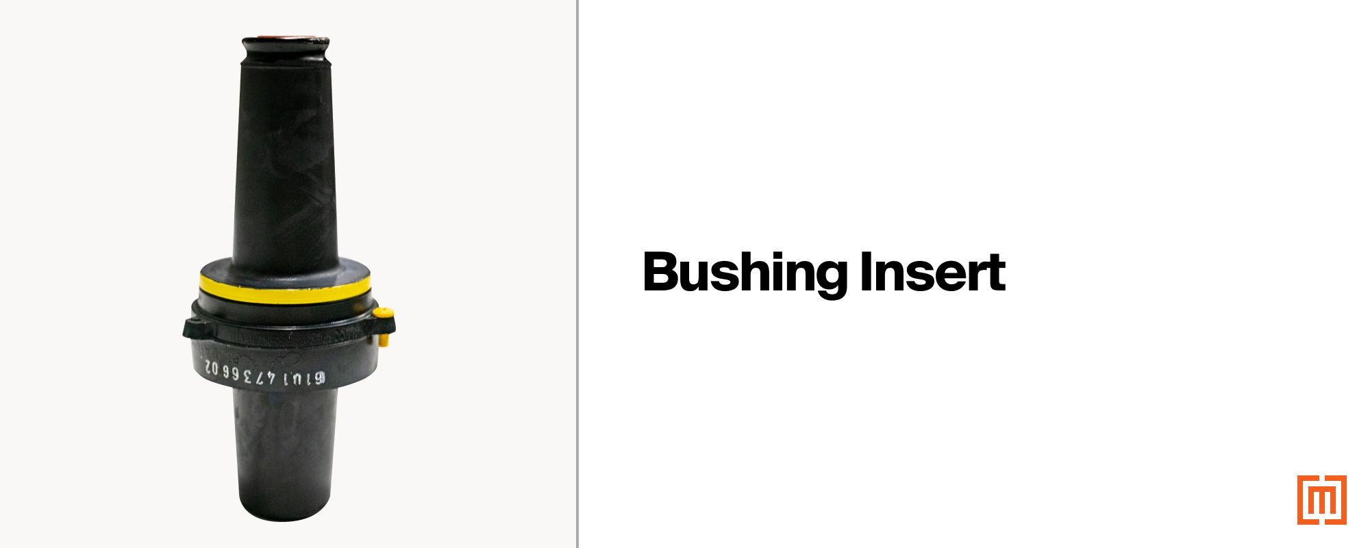
The bushing insert fits into the well and provides the mating surface for cable fitted loadbreak elbows. The base of the insert contains a ⅜” - 16 UNC copper threaded section for screwing onto the well stud. At the front of the threaded base lies a 5/16” hex broach which allows installation with a torque tool. Maximum torque values for tightening inserts are usually provided by the bushing manufacturer. When purchased as a stand alone item, an additional torque tool may be ordered along with the insert to ensure a proper fit into the well. Failure of the bushing well stud may occur if higher-than-specified torque values are applied. As mentioned above, the minimum withstand torque for the copper stud the insert threads onto per IEEE Std 386 is 17 ft. lbs..
The outside of the insert is insulated all the way around with a peroxide-cured EPDM rubber material over a shield housing, which surrounds the inner conductive portion of the bushing. An arc snuffer assembly at the tip of the bushing provides the ability to extinguish an arc when breaking the load at the elbow and bushing apparatus with a hot stick. Between the arc snuffer and hex broach lies an integral contact and piston assembly for transferring current to the bushing well stud; it also ensures proper contact during fault switching and fault-close operations.
Grounding tabs

For safety purposes, grounding tabs are provided for non-integral loadbreak bushing assemblies with a separable insert. During normal operation, a static charge can build up at the insert which could discharge gradually, tracking across the bushing surface, or rapidly with direct contact to a grounded object. A single #14 AWG bare copper drain wire is installed from the grounding tab to an effective connection to ground (typically the metal bushing clamp at the tank wall).
200 Amp Padmount Transformer Bushing Inserts
200 Amp 15 kV Loadbreak Insert

The 200 amp 15kV Class insert is used for voltage applications requiring an insulation rating of 95kV BIL or lower. It is rated for a maximum continuous line-to-line voltage of 14.4 kV and a maximum continuous line-to-ground voltage of 8.3kV. The 15kV loadbreak insert is identified by a red tip surrounding the contact tube.
200 Amp 25 kV Loadbreak Bushing

The 25kV separable bushing insert has a 125kV BIL rating and is suitable for maximum continuous voltages of 26.3kV line-to-line and 15.2kV line-to-ground. A 28 kV rated version is also available for voltage applications requiring a higher voltage rating utilizing a standard 200 amp loadbreak interface. The 25 kV and 28 kV insert is easily identified by the blue tip around its contact tube.
200 Amp 35 kV Loadbreak Bushing (Large Interface)

The large interface 35kV loadbreak bushing (Figure 7–Interface 8 in IEEE Std 386-2016) utilizes a one piece integral bushing with no separable well and insert. It carries a 150 kV BIL rating, and it is suitable for continuous voltages up to 36.6kV line-to-line and 21.1kV line-to-ground. This type of bushing can also be identified by its purple tip near its locking groove (also referred to as the “purple cuff” or “large” version within the family of 35 kV loadbreak bushings).
200 Amp 35 kV Loadbreak Insert (Small Interface)

Unlike its counterpart, the small interface 35 kV bushing (Figure 9–Interface 7B in IEEE Std 386-2016) is made up of a separable well and insert. The small interface 35kV insert has the same 36.6kV max line-to-line and 21.1kV line-to-ground rating. The small interface insert is identified by its longer length and the yellow tip around its contact tube (also commonly called the “small” version within the family of 35 kV loadbreak bushings.
600 Amp Deadbreak Bushing Interface
For primary transformer applications requiring a current rating above 200 amps, a 600 amp non-loadbreak (deadbreak) bushing is used. Deadbreak connections are also often required for HV connections with cable sizes 250 kcmil and above. Unlike the loadbreak interface, the deadbreak does not allow the load to be broken at the bushing. In order to disconnect HV cable connections at the transformer, current flow must be switched off upwind of the HV cables.
With deadbreak bushings, cable connectors are threaded onto the bushing with a metal stud. Another distinctive feature of deadbreak elbow connectors is that they allow for back to back cable splices at a single bushing (this is also referred to as piggybacking cables). All deadbreak bushings are built to conform with IEEE Std 386.
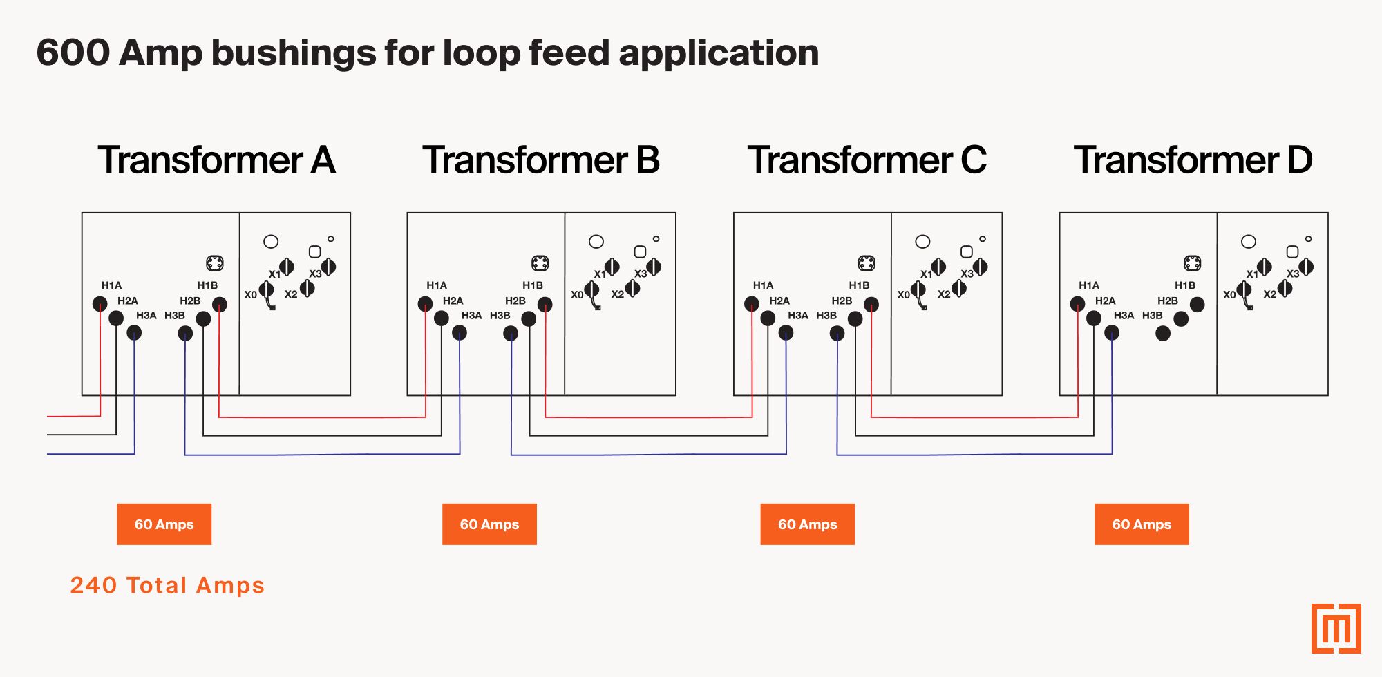
600 Amp bushings are required in loop feed transformer applications where there are multiple transformers in the loop. The bushings in the first transformer in the loop must support the amperage of all the downstream transformers in the loop. In the below diagram, “Transformer A” would require at least 600 amp deadbreak bushings since there is a total of 240 amps in the loop.
600 Amp Padmount Transformer Bushing Inserts
600 Amp 15/25 kV Deadbreak Bushing

The 15/25 kV deadbreak bushing conforms to the requirements of IEEE Std 386, and it is compatible with 15kV Class (8.3kV Line-Ground), 25kV Class (15.2kV Line-Ground), and 28kV Class (16.2kV Line-Ground) applications. It is an integral one-piece style bushing. As with all integral style bushings which are one piece, no drain wire is needed from the exterior of the bushing to ground.
600 Amp 35 kV Deadbreak Bushing
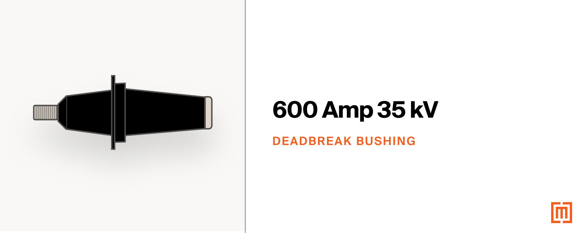
The 35kV deadbreak version, like the 15/25kV, is an integral type bushing, rated 35kV Class (21.1kV Line-Ground). It is longer than the 15/25kV version, but a ⅝” stud is used for both.
600A / 200 Amp Reducing Tap Plug

Some applications will require 200 amp loadbreak components to be fitted onto a 600 amp deadbreak interface. To accomplish this, a special adapter called a reducing tap plug is used. One end of the adapter is identical to the 600 amp bushing at the transformer, while the other end is configured to match the bushing interface of a 200 amp load break connection (available with 15kV, 25kV, and 35kV versions). Because the 600 amp end of the reducer is identical to the bushing at the transformer, a connection must be made with a deadbreak T-Body elbow or bushing extender.
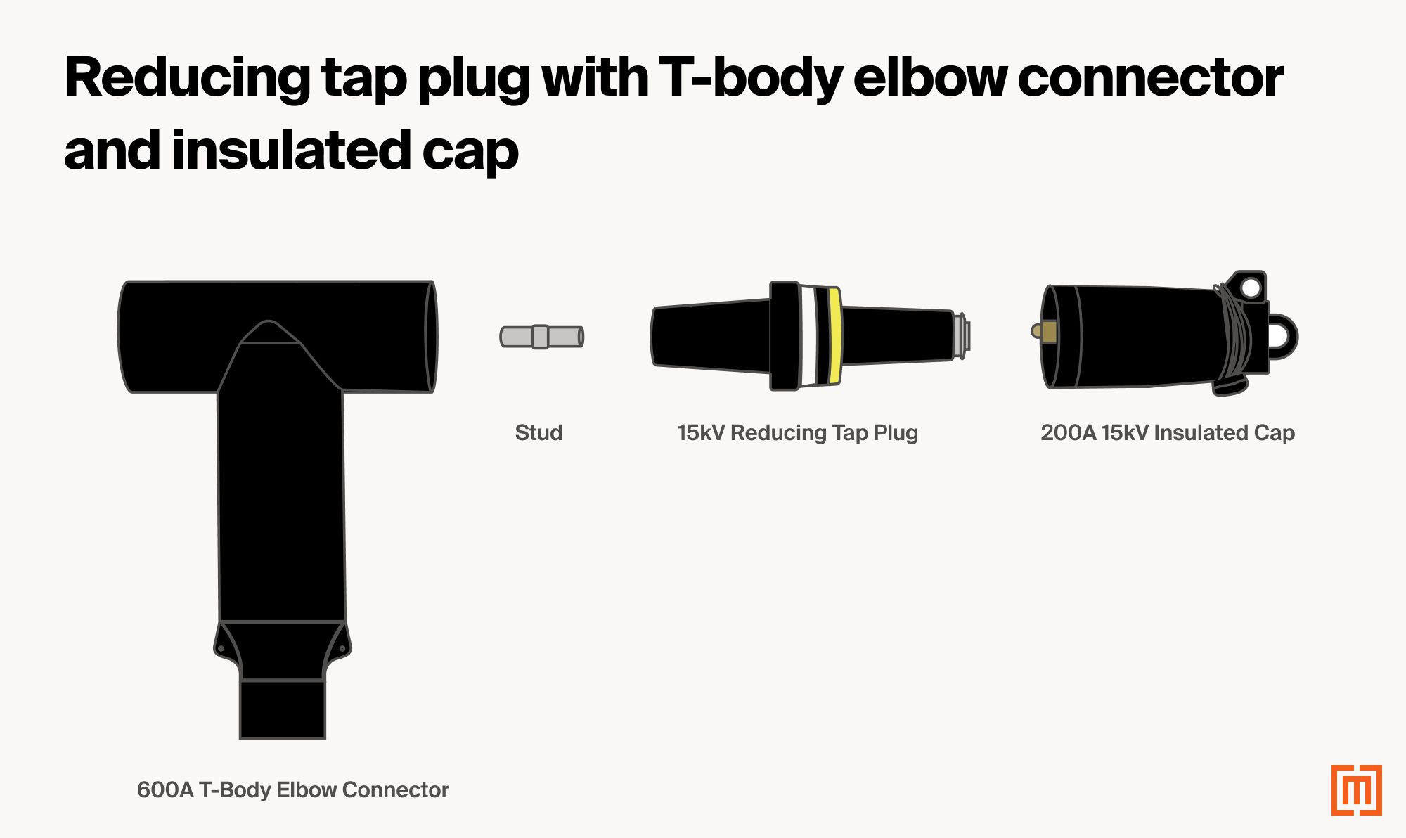
(Picture of 15kV reducing tap plug connected between 600A T-body elbow connector and 200A 15kV insulated cap)
The T-Body elbow provides a connection point for the 600 amp end of the reducing tap plug along with a concurrent cable termination point. The T-Body elbow may be used to connect the reducer in conjunction with cable connections at the same transformer bushing.
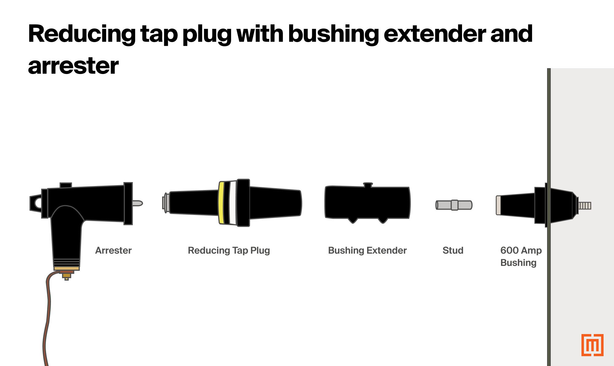
If a standalone 200 amp component is required with no cable connection at the transformer bushing, a bushing extender is used to connect the 600 amp end of the reducer to the bushing at the transformer faceplate. An example of this would be in the case of a six bushing transformer with three cables and three arresters connected at each bushing in the HV cabinet.
For 600 amp bushing applications requiring surge arresters, a reducing tap plug is utilized to allow for the installation of standard 200 amp loadbreak arresters. For 600 amp applications where a reducing tap plug is required for arresters, provisions for additional cabinet space should be taken into consideration.
Watch our video below on the different types of transformer dead front bushings and applications.
Types of padmount transformer Secondary/LV Bushings
Secondary transformer bushings come in many shapes and sizes to meet the diverse voltage and load requirements from project to project. Typical options range from 4 to 24 holes. The configuration of the holes (regardless of number) is universal with a standard hole size of 9/16” and a square spaced pattern of 1 ¾” x 1 ¾” for use with any standard 2-hole compression or mechanical lug. For larger bushings such as a ten-hole spade, secondary supports are installed at each terminal. The conductor is constructed of tin-plated copper.
Padmount Spade Bushings
There are many types and styles of secondary bushings for pad-mounted transformers. For low voltage secondaries 600 volts and below, the size of the bushing increases with the size of the transformer kVA. A 500 kVA transformer will have 4-hole spades, whereas a 2500 kVA will usually have 10 to 12 holes at each spade. As the rated secondary current of the transformer increases, more current carrying capacity is required for the conductors serving the load (meaning more cables at each spade).
For smaller bushings requiring fewer hole spades, a separate bushing with a screw on spade is commonly used. When required, secondary bushing supports are used to support any additional weight not supportable at the tank wall.
6-hole spade bushings

12-hole spade bushings

Universal NEMA Square Hole Pattern
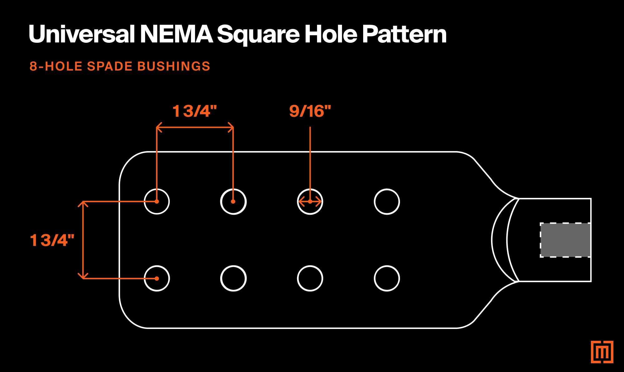
For ease of installation, secondary spades are configured with a universal square hole pattern with 9/16” holes and 1 ¾” x 1 ¾” spacing from center to center. This pattern is compatible with all standard 2-hole compression and mechanical lugs.
As a general rule, if cable connections are made on both sides of the LV spade with two hole compression lugs, the number of holes on each spade equals the maximum number of cables allowed per phase. Each spade is constructed of tin plated copper and designed for compatibility with both copper and/or aluminum cables.
Conclusion
Still wondering which transformer bushings are right for your application? Contact one of our sales representatives today and we’ll help you find the best solution for your particular project. Maddox has the largest inventory of new & reconditioned transformers, as well as the shortest lead times in the industry. We’re committed to helping our customers find the transformers and parts that best fit their needs!