


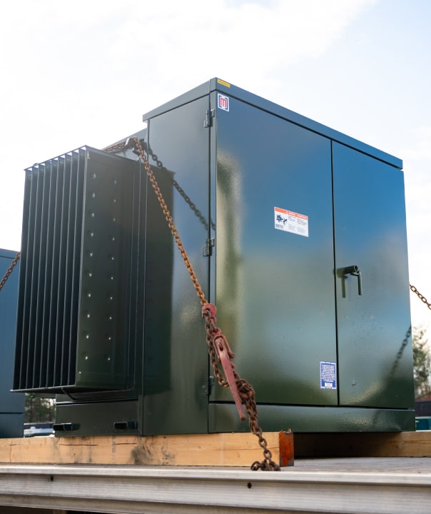
Step-up vs. step-down, what's the difference?
Simply put, transformers are machines that step voltage up or down so that electricity can be moved and used more efficiently. In this article we will review the differences between step-up and step-down transformers, but if you want to learn more about transformers in general, check out our introduction to electrical transformers.
A “step-down transformer” is used to step voltage down, while a “step-up transformer” is used to step voltage up.
The voltage coming into the transformer from the power source is called the primary voltage and the voltage going out of the transformer is called the secondary voltage.
What is a step-down transformer?
A step-down transformer is a transformer that has a primary voltage that is higher than the secondary voltage.
To illustrate, let’s say your building receives 3-phase 480v power from the power company, but you have a piece of equipment that requires 208v 3-phase power. To make this work, you need a step-down transformer to convert the 480v power to 208v to power your machine with the right voltage.

What is a step-up transformer?
A step-up transformer is a transformer that has a primary voltage that is lower than the secondary voltage.
So, if your building is wired with 208v but you need 480v to power a large machine, you'll need a step-up transformer to boost the voltage from 208v to 480v.

These examples are of small industrial applications, but the principle applies no matter the size. For example, power companies use massive substation transformers called GSU transformers (generator step-up) to step voltages up from power plants at 7,200v to extra-high voltage like 345,000v for large-scale power transmission over many miles. Once the power has reached its destination, a substation transformer is used to step the voltage back down for distribution.

Because transformers operate with AC electricity, all transformers are technically capable of both step-up and step-down operations. In this sense, the “step-up” and “step-down” designation simply refers to the way the transformer is being used.
NOTE: AC stands for alternating current, which means that the direction of the current flowing through the system literally changes direction 60 times per second. That frequency of change is measured in hertz, which is why AC systems in the US are called 60 hertz. Read more about the history of AC power vs. DC power.
What are the design differences between step-up and step-down transformers?
Any transformer can theoretically be used for either step-up or step-down operation. However, there are some notable differences in the way that step-up and step-down transformers are designed. These are not hard-and-fast rules, but are standards the transformer industry tends to adhere to. Further, design differences tend to be more pronounced in low-voltage transformers (<600v) as compared to their medium-voltage counterparts (>2400v).
NOTE: Step-up transformers designed specifically for solar and wind farms have their own set of design standards, which we will explore in a future article.
Here are the main design differences broken out by transformer type:
1. Winding and voltage tap location
Low voltage transformers
Low voltage (<600v), step-down transformers usually have the high-voltage windings on the outside, and low-voltage windings on the inside. Step-up transformers have the opposite configuration. The main reason for this is that the voltage adjustment taps are located on the primary windings, and since the windings are concentric (one inside the other), the windings with the voltage taps have to be physically located on the outer coils.
Below is an example with the high voltage windings shown as red, and the low voltage windings shown as blue.

Medium voltage transformers
When it comes to medium voltage transformers, there is virtually no difference in winding or tap locations. HV windings are always on the outside, and taps are always on the HV side.
2. Vector grouping
Low voltage transformers vector grouping
Low voltage transformers are usually built with a DELTA-WYE vector group regardless of step-up or step-down operation, with DELTA being the connection on the primary side, and WYE being the connection on the secondary side.
Below is an example showing the same low voltage transformer, but one is designed for step-down, and the other for step-up.
Medium voltage transformers vector grouping
Medium voltage transformers are usually built with a DELTA-WYE vector group when designed for step-down operation, and with a WYE-WYE vector group when designed for step-up operation.
Below is an example showing the same medium voltage transformer, but one is designed for step-down, and the other for step-up.
3. Reverse feeding
Step-down transformers are occasionally used as a step-up transformer by “reverse feeding” or “back feeding” the transformer.
Reverse feeding is simply a matter of having the power supply enter at the low voltage windings.
Given the greater availability of step-down transformers, reverse feeding is a fairly common practice. With that said, there are some important things you should consider before making the decision to reverse feed.
There are four main issues with reverse feeding:
Code compliance
NEC 450.11 (B) permits a transformer to be fed from the secondary side of the transformer as long as the installation complies with the manufacturer's instructions. The code reads as follows: "A transformer shall be permitted to be supplied at the marked secondary voltage, provided that the installation is in accordance with the manufacturer's instructions."
This is typically the reference that is cited for reverse feeding transformers by inspectors to ensure an installation complies.
So while there’s nothing in the NEC that directly prohibits reverse-feeding, your local electrical inspector may decide they want to see language on the transformer nameplate like “suitable for step-up operation” or “rated for bi-directional use” before approving the installation.
Voltage Taps
Transformer voltage taps are included by default on the primary windings. When you reverse feed a step-down transformer, you lose the ability to adjust the primary voltage rating to accommodate for small discrepancies in the supply voltage. And if there is more than a 5% variance, the windings will over-excite causing excess heat and energy loss. This can result in either saturation of the windings, or a failure to produce secondary voltage.
Inrush
Inrush current (the amount of current the transformer draws when initially energized) can be up to 16 times greater when reverse-feeding, which could result in nuisance tripping of fuses and circuit breakers.
This greater inrush occurs because normally the output winding is wound first and is therefore closest to the transformer core. When a transformer is back-fed, the inner winding is energized first.
Sizing a larger breaker for the excess load may violate code. The greater the kVA the greater the inrush, which is why some manufacturers recommend you only reverse feed transformers 75 kVA and below.
Vector grouping / No neutral
The most common transformer vector group is DELTA-WYE, with DELTA being the configuration on the primary side, and WYE on the secondary side. Therefore, reverse feeding a transformer originally designed for step-down operation will result in a DELTA secondary connection, which lacks a neutral.

Most isolated electrical circuits must be grounded (usually with a bonded ground to neutral). This requires a wye connection at the source transformer. Reverse feeding a delta wye transformer puts the delta winding in front of the isolated circuit instead of the wye. This may work, but introduces problems when configuring overcurrent protection for the load. See the article Putting It In Reverse by James Stallcup for more reading on this subject.
Should you reverse feed a transformer?
Our recommendation is that you buy a purpose-built step-up transformer instead of reverse feeding when possible. If you run into a situation where you need to reverse a transformer, make sure it meets the above criteria and use a licensed electrician. And as always, if you have questions or need more help when it comes to understanding or finding the right step-up or step-down transformer, don’t hesitate to contact us or call our team at 1-866-719-1882.
.jpg)


